
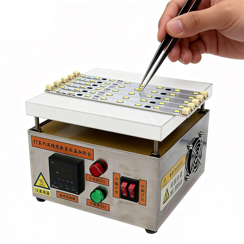
The heating platform (also called preheater or rework station) is an essential tool in the LED industry, particularly for soldering and repairing LED components on Aluminum Substrates (MCPCB). It solves the soldering challenges caused by the high thermal capacity and excellent thermal conductivity of aluminum substrates.
Aluminum Substrate Structure: From top to bottom: LED Chip/Circuit Layer → Insulating Dielectric Layer → Aluminum Base Layer.
The Problem
When heating solder joints directly with a soldering iron or hot air gun, heat is rapidly “siphoned away” by the underlying aluminum material. This prevents the solder joint from reaching the required melting temperature of solder paste (approximately >217°C), leading to cold solder joints and poor electrical connections.
The Solution
The heating platform provides uniform bottom heating to preheat the entire aluminum substrate to a stable “base temperature” (typically 120-180°C, depending on solder paste and process). This achieves:
- Heat compensation to counteract aluminum’s rapid heat dissipation
- Easier local temperature elevation for subsequent soldering or removal operations
- Uniform heating to prevent board warpage or uneven component heating
1. Standard Operating Procedure
For Soldering New LED Components
2.1 Preparation
- Heating Platform: Set temperature according to solder paste melting point and board thermal mass
- Aluminum Substrate: Clean pads, remove oxide layer and old solder residue
- LED Components: Verify polarity and specifications
- Solder Material: Recommended solder pastes:
- Low-temperature solder paste (e.g., Sn42Bi58, melting point 138°C)
- Lead-free solder paste (e.g., Sn99Ag0.3Cu0.7, melting point ~217°C)
- Tools: Anti-static tweezers, high-temperature tape, temperature measurement device
2.2 Bottom Preheat
- Place aluminum substrate in the center of the preheated platform, ensuring good contact
- Wait 3-8 minutes (depending on board size and thickness) for uniform temperature stabilization
- Always verify actual board surface temperature with a measurement device (should be 20-40°C below solder paste melting point as preheat temperature)
2.3 Soldering Execution (Two Main Methods)
Method A: Preheat Platform + Hot Air Gun (Most Common & Flexible)
- Apply solder paste or place solder wire on preheated board pads
- Precisely position LED components with tweezers
- Use hot air gun (300-350°C, low airflow) to locally heat the top of components until solder melts and components “self-align” into position
Method B: Pure Heating Platform Reflow (Suitable for Small Components or Batch Processing)
- Print/apply solder paste on pads and place components
- Increase platform temperature from preheat to reflow temperature (20-30°C above solder paste melting point, e.g., 160-170°C for 138°C solder paste)
- Observe solder melting and component alignment, then begin cooling
- Note: This method requires precise temperature control and uniform heating
2.4 Cooling & Inspection
- Key: Allow workpiece to cool naturally and slowly on the platform or on a dedicated cooling plate
- Avoid forced cooling with air or water to prevent thermal shock damage
- After cooling, perform electrical testing and visual inspection
3. Typical Repair Case Studies
Case 1: Single LED Failure (e.g., Ceiling Light, LED Strip)
Symptom: One LED not working, causing entire series to fail (except in parallel design).
Repair Procedure:
- Removal: Secure board on preheated platform (at preheat temperature, e.g., 150-160°C, not directly at high melting temperature). Use hot air gun to concentrate heat on failed LED until solder melts, then quickly remove with tweezers.
- Cleaning: While still hot, clean pad residue with soldering iron to create a flat surface.
- Soldering: Follow standard procedure to solder new LED component.
Key Principle: The heating platform provides “heat support” to prevent heat dissipation; final removal heat comes from the top heating tool.
Case 2: Multiple/All LED Replacement (e.g., Retrofit or Batch Repair)
Situation: Upgrading color temperature, brightness, or batch repair.
Repair Procedure:
- Bulk Removal: Preheat board to 150-160°C. Use hot air gun with large nozzle to heat entire area, remove all LEDs with tweezers or scraper.
- Thorough Cleaning: Use desoldering braid or soldering iron to completely clean pads while board is preheated.
- Batch Soldering: Apply solder paste through stencil, precisely place all new LEDs, then use either:
- “Preheat platform + hot air reflow” method
- Pure platform reflow method (heating platform temperature raised to reflow temperature)
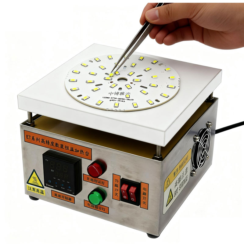
Case 3: LED COB (Chip-on-Board) Module Repair
Characteristics: Large chip area, extremely high requirement for temperature uniformity, solder joints under chip, difficult removal.
Repair Procedure:
- Precision Preheat: Set preheat temperature accurately and uniformly (typically 145-155°C). Allow sufficient time (5-10 minutes) for entire large substrate to heat through.
- Removal: Use hot air gun with large nozzle to uniformly heat entire COB chip area. Ensure bottom solder is completely melted before carefully lifting. Handle gently to avoid damaging ceramic substrate or underlying circuitry.
- Soldering: Apply thermal paste and solder paste on cleaned pads. Place new COB light source. Use “bottom preheat + top heating” method for soldering.
4. Key Considerations & Techniques
Temperature is Critical
- Distinguish between preheat temperature and reflow (soldering) temperature
- Always start low and gradually increase
- Always use temperature measurement tools to monitor actual board temperature, not just platform display
ESD Protection
- LED components are electrostatic sensitive devices
- Work on ESD-safe mat with grounded wrist strap
- Use anti-static tools and materials
Avoid Thermal Shock
- Follow “heat slowly, cool slowly” principle
- Avoid placing cold board directly on hot platform
- Never use forced cooling after soldering
- Thermal shock can cause substrate warpage or internal chip cracking
Safety & Ventilation
- Soldering produces harmful fumes – ensure adequate ventilation or use fume extraction
- Heating platform surfaces are extremely hot – always use thermal gloves or tools
- Keep flammable materials away from work area
5. Solder Paste Temperature Reference
| Solder Paste Type | Composition | Melting Point | Platform Preheat Temp | Platform Reflow Temp | Application Notes |
|---|---|---|---|---|---|
| Low-Temperature | Sn42Bi58 | 138°C | 150-160°C | 160-170°C | Recommended for heat-sensitive components |
| Lead-Free | Sn99Ag0.3Cu0.7 (SAC305) | 217-220°C | 190-210°C | 220-240°C | Industry standard, good mechanical strength |
| Lead-Free with Bi | SnAgCuBi | 205-215°C | 180-200°C | 210-230°C | Lower melting than standard SAC |
| Tin-Lead | Sn63Pb37 | 183°C | 160-175°C | 190-210°C | Excellent wetting, legacy applications only |
6. Summary & Key Success Factors
Core Value: Heating platform overcomes aluminum substrate’s rapid heat dissipation through uniform bottom preheating, enabling safe, efficient, and high-quality LED soldering and repair.
Success Depends On:
- Precise temperature control – understanding preheat vs. reflow temperatures
- Measurement validation – using temperature measurement tools
- Patient execution – following gradual heating and cooling cycles
- ESD protection – safeguarding sensitive LED components
- Proper tool selection – matching method to component and situation
For professional repair technicians or small-batch producers, a temperature-controlled, evenly-heating platform with sufficient area is an essential tool for working with LED aluminum substrates.


